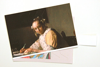
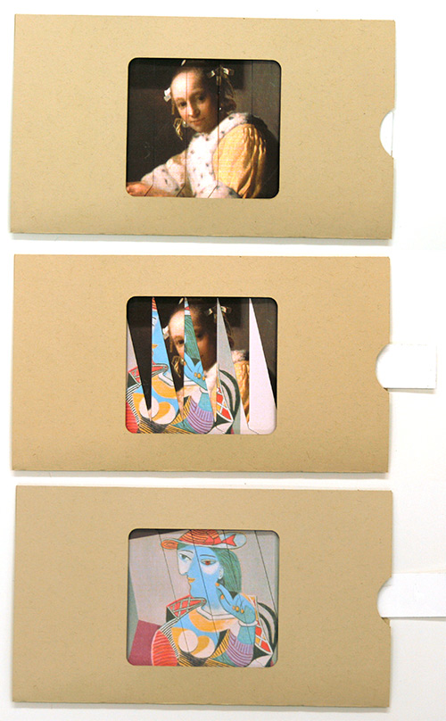
This mechanical paper structure is called a dissolving view — you pull a tab to replace one picture with another. First an example of the mechanism working, followed by the instructions for making the structure. The template is based on the one I found here. You might also be interested in Instructions for Dissolving Views, Technique 1.
|
Download the template
In addition, you’ll need
The finished size is 6½” x 3¾”. The picture opening is 2-5/8″ x 2-3/8″. |
|
||
|
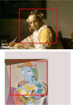
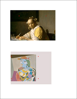
Selecting your pictures: the picture is larger than the opening. It’s easier to do the cutouts below if the picture covers the entire mechanism. The part of the picture that will show through the opening is indicated in red, to the left. You can use your own pictures or the pictures in this example are on the 4th page of the PDF. | ||
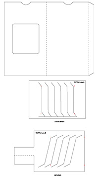
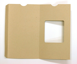
| Print page 2 of the pdf you downloaded, onto cover stock paper. Cut out the template along the solid lines, fold along the dotted line and set aside. |
 |
||
 |
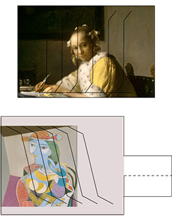
Print page 3 of the template onto cover stock paper. With your awl, needle or push pin, make holes in the paper at the red dots. Turn the paper over and glue your pictures onto the paper so that the part you want to dissolve is centered in the box made by the pin pricks. Picture A, which you’ll see when the mechanism is closed, goes in the top box. Picture B, the dissolve, goes in the lower box. | ||
| Turn the page over and cut along the solid lines. Use a sharp xacto knife, taking care to cleanly cut the joints. Cutting against a metal ruler will help you keep the incisions straight. Be sure to cut through both the template and your glued-on picture. Turn over the pieces and they should look like this: |
|
||
| Score, fold & glue the pull tab on the moving piece. | |||
| |||
|
|||
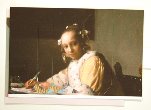
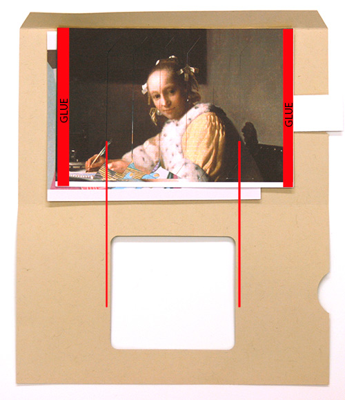
| Position the mechanism inside the cover so the top aligns with the fold and the tab is in the middle of the thumb cutout. Adjust the position of the mechanism so that the outer cut lines on the top picture align with the cutout window (see red lines on photo below). Put glue on the sides of the top picture (see red bars below), taking care not to get glue on the cuts or bottom mechanism. Put glue on the outside of the folded tab on the sleeve. Fold the tab in and then close the cover. Use a bone folder or your hand to seal the glue. | 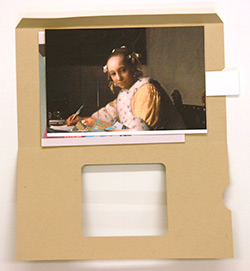
|
||
|
|||
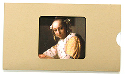
| You’re done. Carefully pull the tab out to see the second picture. You may need to wiggle the tab a bit the first time to get the mechanism moving. The glue on the top picture and the sleeve should keep the mechanism from falling out of the sleeve. |
 | ||